
Normal digital image photography is performed using the OS-9 monitor and the Photo button on the JEOL control unit. This allows you to acquire the current image as displayed on the OS-9 monitor.
The JEOL Mapping software is used to perform either beam or stage scanning for automated image acquisition of multiple images simultaneously. The JEOL Mapping routines allow you to:
Acquire digital beam and or stage scanned maps of digitized positions
Multiple video sources can be acquired (one video source per mapping pass)
Multiple WDS and EDS X-ray maps can be acquired (up to 5 WDS maps per pass, and up to 8 EDS elements per pass)
The maximum number of simultaneously acquired maps is 16
Map runs are set up for acquisition using the JEOL EPMA Main Menu, Analysis, Map Analysis. Maps are viewed either during or after acquisition using the JEOL EPMA Main Menu, Process, Map Analysis.
Select JEOL EPMA Main Menu, Analysis, Map Analysis, this will open up the Map Analysis window:
Click on Sample to open up the Map Analysis directory window. The window will display the sample file located in the group that the last person was using.
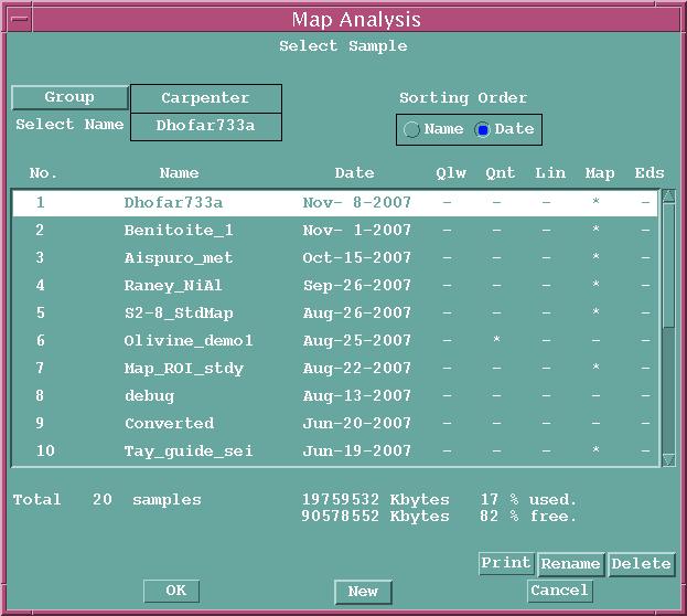
If you are setting up a mapping run in the same Group, you do not need to navigate up to a higher Group. To change groups, click on Group and select the desired Group or create a new Group (the Group is the last name of the user).
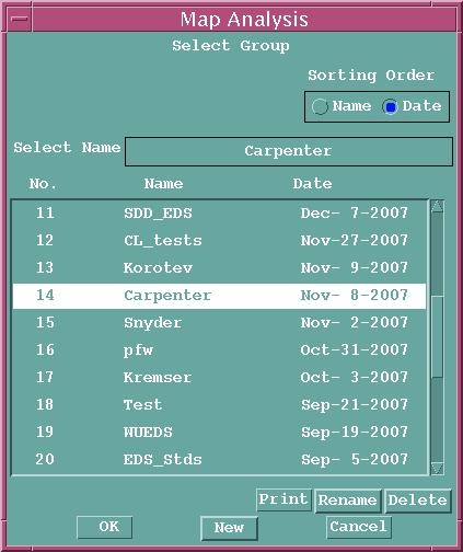
For this demo we set up a Sample named Map_demo1 in the Group Carpenter:

This window will be used for all subsequent operations to set up the mapping run by selecting the appropriate submenu from the Measurement menu in this window:
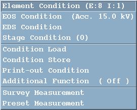
The sub menus of the Measurement menu are used for the following:
Element Condition (E:N I:N)
Select the elements to be mapped using WDS and/or EDS, and select any video
image source that is to be mapped
Select the Measurement Order for WDS elements (this really will be established
in the WDS Condition setup)
Select the Condition for the WDS and/or EDS elements.
For WDS elements these Conditions are the specific element name, x-ray line, spectrometer
(called channel), crystal, spectrometer position in mm, PHA gain, detector
voltage, baseline, window, SCA mode (Differential vs. Integral), and measurement
sequence in the mapping run.
For EDS elements the Conditions are the element name, x-ray element label, x-ray
line, number of regions of interest, low limit of ROI in keV, high limit of ROI
in keV, low limit of second ROI (if used), and high limit of second ROI (if
used).
EOS Condition (Acc XX.X kV)
Select the EOS Conditions to be used for the mapping run. This includes the
accelerating potential in kV, probe current expressed in scientific notation
(in amps), magnification, probe diameter in microns, scan conditions (scan
mode, scan format, scan speed, and other parameters that are usually read
rather than set.
EDS Condition
The EDS Condition settings are typically read from the EDS Condition window in
order to satisfy the mapping setup. It
is important that the desired aperture be in place especially for quantitative
analysis, since a correction is made for aperture number in the quant analysis.
Stage Condition
The Stage Condition window shows the number of stage positions that have been
set for the current mapping run. These stage positions are used for both beam
and stage maps, meaning that a specific xyz location is used as the position
for map acquisition regardless of it being a beam raster or stage raster map.
The Stage Condition lists the sub-samples that have been set up for each
mapping run. The window for setting stage positions is opened by clicking on
Pos. Input at the bottom left corner of the Stage Condition window.
Condition Load
This allows a previously saved set of conditions for mapping to be viewed and
loaded in. This Condition file contains WDS and EDS elements, EOS conditions,
etc. It is useful for reading in a set
of elements, but realize that especially for WDS peaks positions and EOS column
conditions you will need to verify that these settings are all correct.
Condition Store
This allows you to save the current set of conditions to a file for later retrieval.Print-out Condition
To print out selected results from a mapping run, generally left unchecked.
Additional Function (On/Off)
Choice of background measurement as part of the mapping run, and choice of
continuous or step scan mode during the stage scan (generally set to continuous
except for very long acquisition times).
End of Mapping document.